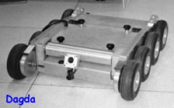
Meet Dagda, which represents a good few years of my past life!
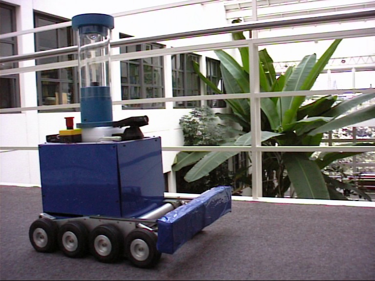 It occurred to me recently that I’ve never put any details of the robot up on the web, so I figured I might as well correct that!
And a post on Dagda’s motion controller linux device driver is now up here
Dagda started life as a donated piece of hardware from Kentree, a small company in Cork who made bomb disposal robots until they were sold on to a British company and then a Canadian one in 2004. It was initially much smaller and designed to drive under cars to look for car bombs: 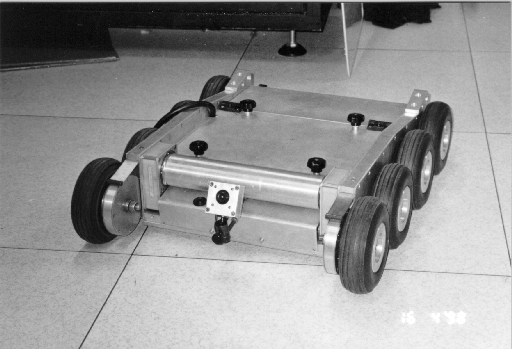 However, for our planned project – which was to research alternative approaches to teleautonomous behaviour – we would need more in the way of sensors than a single CMOS camera, and we would need an onboard computer (the original Dagda was remote-controlled with no onboard processing). There was also the point that as it was supplied, Dagda wasn’t exactly… well, working 😀
 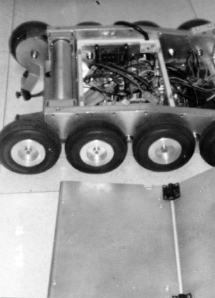 It doesn’t look too horrible, but none of the electronics were functional at all. The physical hardware – the chassis, drive train gearing and wheels – were fine, and the motors were still working too. The CMOS camera sensor might have been functional, but we didn’t have any specs on it or how to interface to it. And what circuitry was in the chassis was basicly toast on arrival. I was of the opinion that the hardware should be dumped and a COTS system bought in; my supervisor thought it’d be a lot easier to just use the chassis as a base to build a new research platform on. So first things first, gut the robot of all broken circuits and see what’s left.
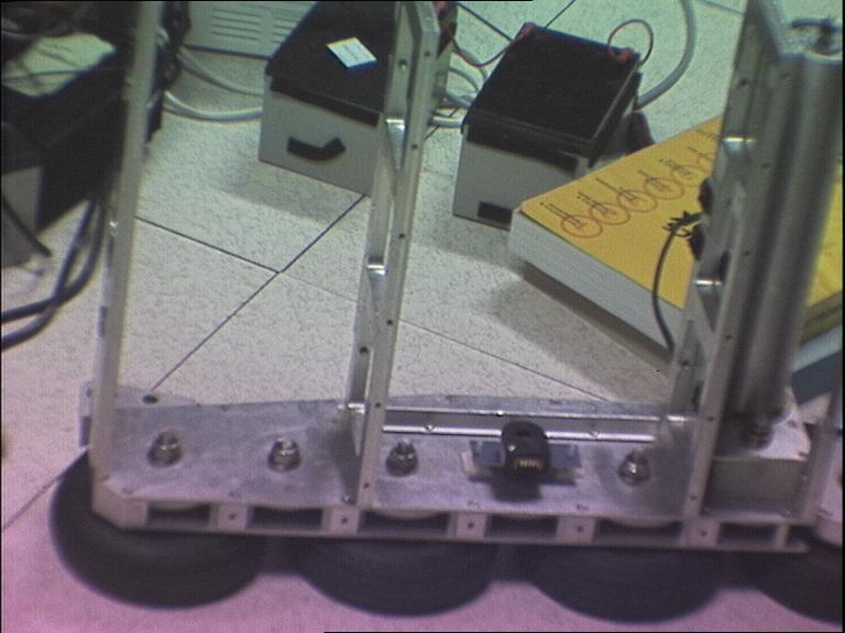 Not very much, as it turns out. In fact, the encoder mounts you can see in the middle of the main chassis compartment’s sidewall, while working, had to be dumped as well because they were attached to the drive chain rather than to a freewheeling wheel – so they had no way of telling if wheels were slipping or not. They could sense if the wheels were fully locked, but that wasn’t of much use to anyone (odometry is notoriously inaccurate even under the best of circumstances, but when all you’re sensing is a gear in the drive train, it’s almost a waste of time). So they would have to go and be replaced by sensors on the two free-wheeling wheels at the front of the chassis.
So, starting from the basics, the design had to have a power source as the robot was to be autonomous and tether-free. That meant lead-acid batteries, and they had to physically fit in the battery compartment and provide enough power to run everything for at least an hour so we could get experimental runs long enough to produce useful data. I also wanted to monitor voltage and current levels and condition the voltage levels because I knew that was going to be a problem later on. Next was motion – we had motors, and they were fine (if a bit odd, they were truck windscreen wiper motors). We’d need motion control though. We’d also need odometry, as mentioned before. We also wanted sensors – cameras, and a laser scanner for measuring distances. There was also to be sonar (though that was later dropped because it was about as noisy as the odometry and far less convenient). We would also need some sort of computer for running the whole system, obviously enough. Bear in mind that this is 1997 we’re talking about here, and small cheap computer platforms with enough oomph to do image processing and motion control didn’t really exist. So we went with a then top-of-the-line PC104+ platform running linux. Which was not cheap.
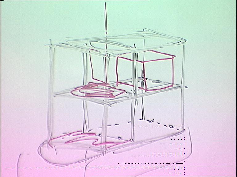
And of course, all that kit has to be bolted somewheres, so the chassis had to be enlarged with an extension frame. Design sketch time!
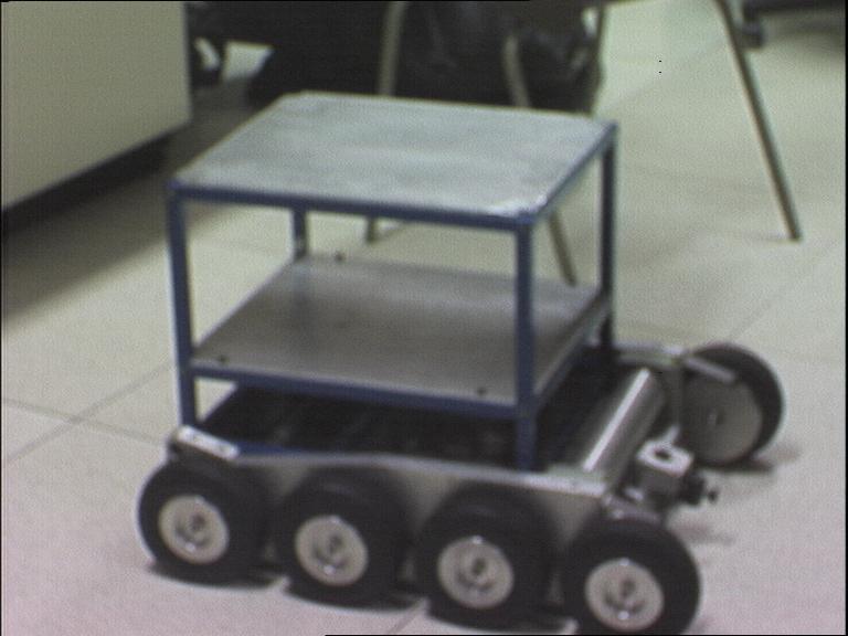
Now we had no metalworking capabilities at all in the lab (in fact, we had damn near no hardware manufacturing capabilities at all in the lab, which was a bit of a pain for a robotics lab) so we drew up the sketch in a more precise technical format and sent it off to a local light engineering company who built it for a rather extortionate price:
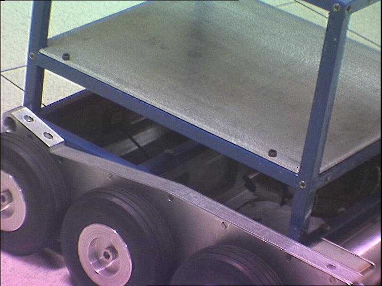
Sorry about the fuzzy photo by the way, this was 1997 and decent digital cameras cheap enough for a postgrad student to afford simply didn’t exist – these photos came from a reasonably high-end camera that could get all the way up to VGA resolution on a good day with a following wind…). The top and middle plates in the frame were removable with allen bolts and side panels could be attached using velcro to make everything look a little less complicated.
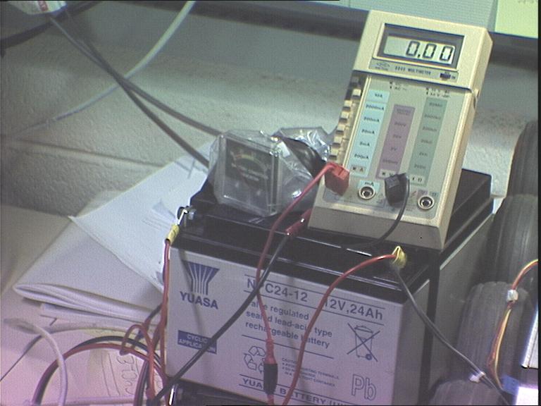
So now we had the basic frame taken care of, it was time to source some batteries.
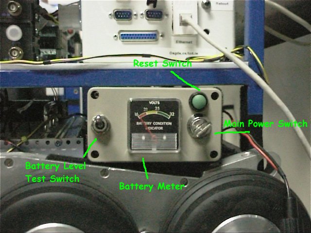
These proved to be way too large, so we did source some smaller ones later on. The meter was to give an idea of the charge level in the batteries and was mounted in its own little power switching box off to one side. Here’s the power switch/meter box in the final build:
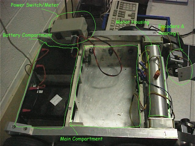
And here’s the final batteries and basic power wiring and some labelling:
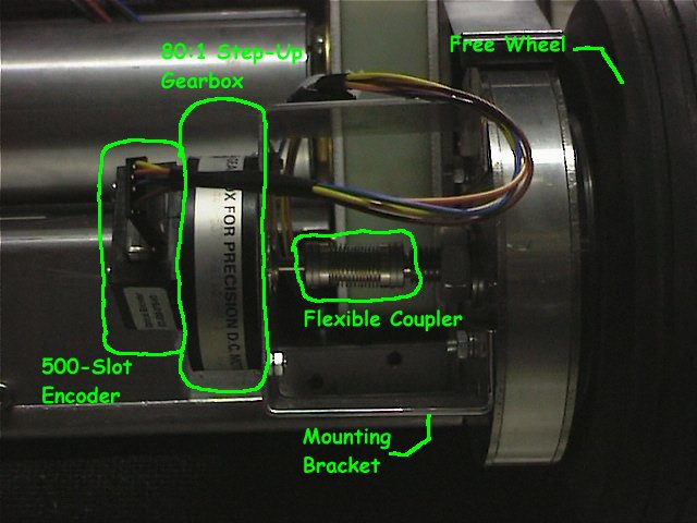
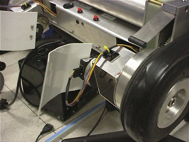
Notice that the front-mounted CMOS camera has been ditched and that the encoders in the main compartment have moved and are now out on the front drive wheels. They may look a bit more complicated; that’s because they are – the mounting was a bit more difficult to arrange:
The two white plastic shields wouldn’t protect against much, but they were only there to protect against casual bumps in the lab, not for actual tootling about outside. Also, those two things on the front of the robot that look like buttons, aren’t – they’re lights to indicate power for the main systems and power for the motors (which were on a seperate, higher voltage rail).
So that’s the frame, the power and the encoders. Next up, the motor control. There’s two parts to this – a PWM source and a H-bridge to do the actual power switching. The PWM source was a COTS solution – a motion control board which I’ll talk more about later. The HBridges turned out to be one of the larger pains in the project, and also a major point of personal development for me 😀
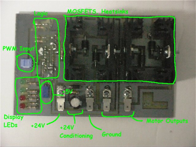
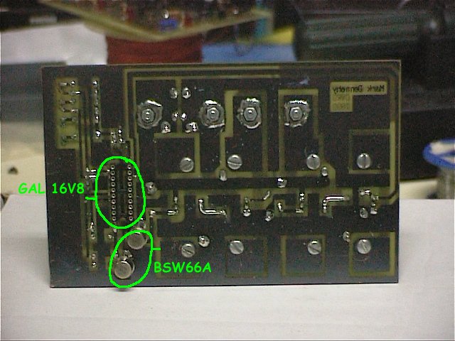
The first stab at this was… a bit weedy. Standard circuit design, using a PAL for the switching logic and some rather underspec’d mosfets for the switches (I’m pretty sure the original design used actual mechanical relays but it was hard to tell from the toasted circuitry that came with Dagda on the first day):
If those heatsinks look a little small, that’s because they are; and if the whole board looks a little home-made, that’s because it is. I did the circuit design and the PCB layout, I etched the board myself (I still have the stains on one of my work shirts – ferric chloride is deeply nasty stuff), I hand-assembled and soldered the board myself, and I got to watch as parts of it melted under full load. So there was symmetry there at least…
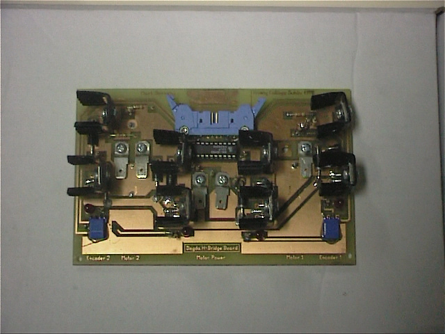
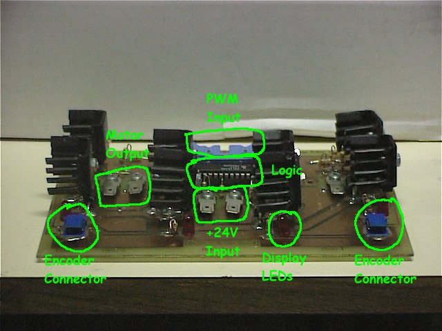
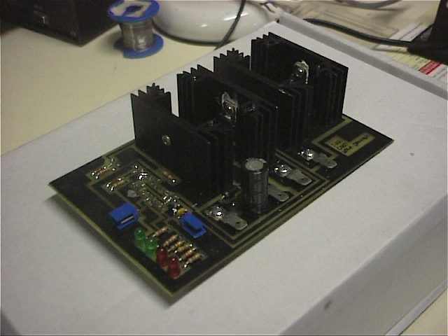
My second attempt was a little better, in fact I think it was quite up to the task:
As you can see, much beefier heatsinks, much better arrangement on the board, much more mechanically robust, and it even had flashing LEDs to indicate function (very 1950s B-movie). Some of you may notice that there’s a mild resemblance between the arrangement of the heatsinks and the barrels of a double-barreled shotgun. This wasn’t actually intentional, it was just how the PCB layout came out in the end. Unfortunately for me, the day before one of our demos, I found that it was a functional similarity as well – the GAL chip which contained the logic was misprogrammed (I had a + instead of a – on some line of code) and instead of switching the power rapidly on and off across the motors, it basicly short-circuited two car batteries across a single transistor. There was an ominous humming noise, and as I looked down on the board wondering what the LEDs were indicating, the MOSFET gave up the ghost and vapourised, superheating the ceramic casing which then explosively shattered – and the heatsinks channeled the fragments straight up past a rather surprised me. I got a nice nick under one eye and learnt the difference between electrical and electronic…
…and I also learnt that this wasn’t what my PhD was about, so for the third attempt, I bought in a COTS H-Bridge board power rated to the appropriate level 😀
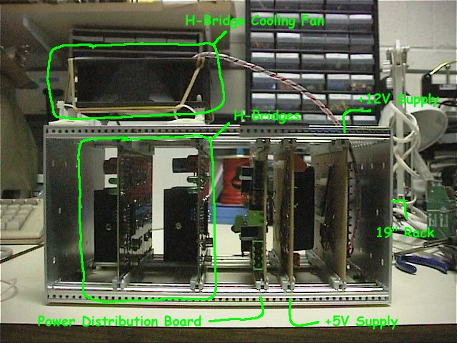
So the HBridges, the 12V-to-5V power convertor (bought off-the-shelf), and a distribution board, all went into a cut-down standard 19-inch rack, which fitted nicely into the main compartment:
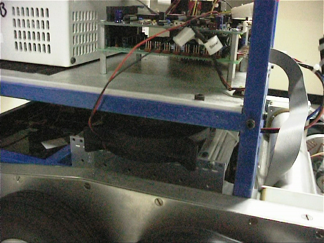
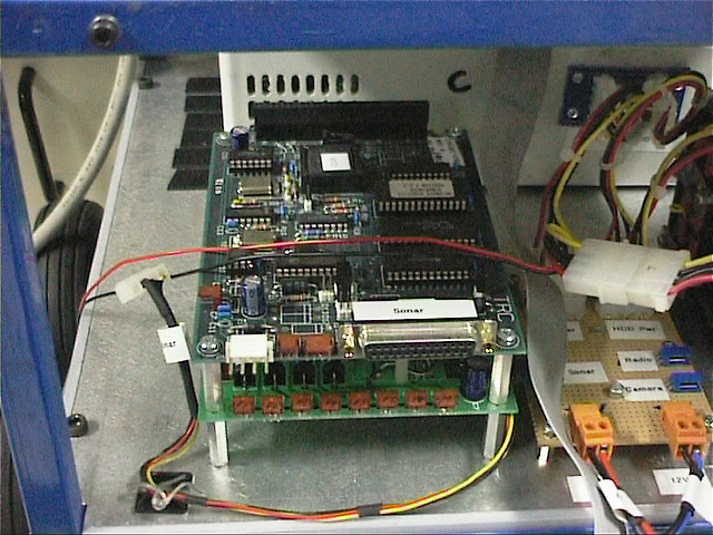
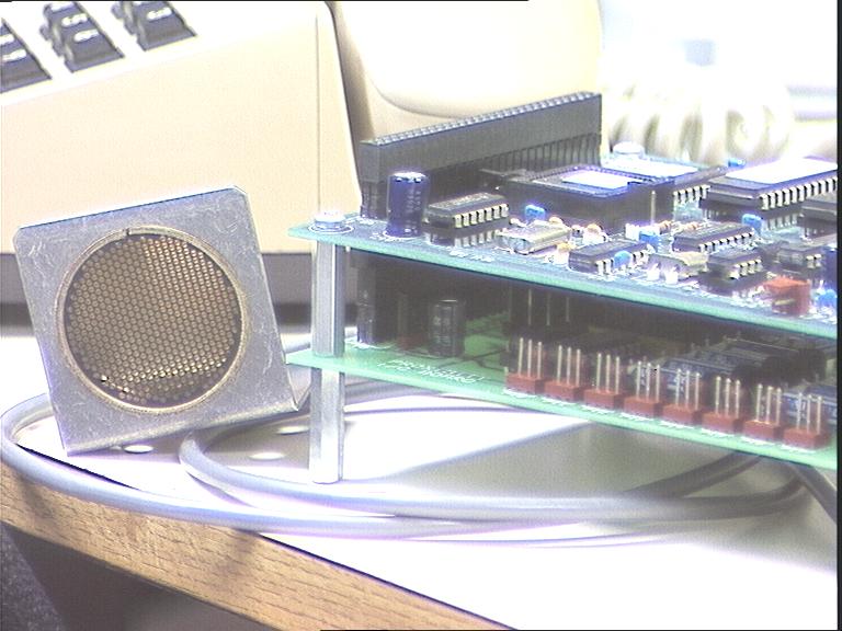
Tucks away very neatly down there. That double PCB you can see on the first level of the extension frame, by the way, was the sonar interface board. Bought in, off-the-shelf, and dumped eventually because the sonar sensors were so noisy (and because we had a laser scanner that was far better than them).
Well, this is going to take more than one post. Next time, I’ll take a closer look at all the cameras we used on Dagda and the main computer that controlled it all.
Tags: dagda, mobile robot, robot

[…] This post was mentioned on Twitter by Mark Dennehy, Mark Dennehy. Mark Dennehy said: #StochasticGeometry Dagda: Dagda, the robot I spent several years of my PhD building – this post is on the main f… http://bit.ly/aqmPR9 […]
[…] « Dagda […]
[…] been blogging about his past (PhD) experiences in the world of robotics (part 1 and part 2). It’s an interesting read, even if only to see how quickly state of the art […]